The Modern Safety Bicycle
By H. A. Garratt189980 chapters106 images
Contents
- Garratt explains that he has confined the book to the ordinary rear-driven safety and to tandems built on the same lines, referring readers wanting fuller coverage to Archibald Sharp's Bicycles and Tricycles. He states he has no interest in the cycle trade, prefers the term "free pedals" to "free wheel," and predicts that for 1900 every maker will fit a back-pedalling rim brake with either a Morrow-type roller clutch or a "Whippet" ratchet; he thanks his assistant Alexander Swanson for the figures and Professor Barrell of University College, Bristol for the proofs.
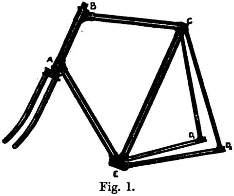
- Names the members of the diamond frame from Fig. 1, steering socket or head A B, bottom bracket E, seat stays C D, chain stays E D, front tie A E, top strut B C and diagonal C E, and sets out the corner lettering used throughout the book. It establishes the saddle corner C as the point carrying most of the rider's weight and the bottom bracket as the frame's most critical casting.
- The three aims are a rigid connection between the handle-bar pillar at B and the crank spindle, so that hill-climbing effort is not wasted springing the frame; an equally rigid connection between the bottom bracket and the back hub, since flexure there throws the chain out of line; and sufficient strength to carry the rider and absorb road shock.
- Shows with Fig. 2 that pedalling hard while pulling on the handles distorts the unbraced quadrilateral A B C E, and that stiff joints plus large-diameter tubes resist this less efficiently than an added diagonal from A to C or B to E. Fig. 3 illustrates the sideways bending caused by pedal force applied outside the central plane, and Fig. 4 a duplicated diagonal B E splayed at the bottom bracket, a scheme resembling the "Elswick" frame, which instead duplicates the front tie A E.
- A high frame lowers the stresses in the main members but is harder to keep true sideways, the joints taking a permanent set that throws the head out of line with the diagonal C E. Garratt argues that bracing the front quadrilateral with a diagonal A C is a better answer than the extra tube parallel to A C used by some makers.
- Uses a spring-balance experiment, a 4 lb. weight placed suddenly in the pan swings the pointer to about 8 lbs., to show that shock loads far exceed static loads, and that a wheel striking a stone loads the frame similarly. He concludes that critical strengths are settled by experience, calculation being confined to distributing material for maximum strength per unit weight.
- Opens the long chapter on frame construction, lugs, brazing, chain adjustments, the bottom bracket and the strength of tube sections, beginning with the three ways of making a frame joint.
- Introduces the three usual methods of forming frame corners: stamped steel lugs, malleable iron castings and lapped tubes, each treated in turn in the following sections.
- A solid billet of steel is drop-stamped hot between dies to the external shape (Fig. 6), then bored at the correct angles to fit the tubes exactly. Good steel stampings make an excellent joint but are costly, because so much metal has to be machined away.
- The cheaper alternative: lugs cast hollow and nearly to finished thickness, then decarburised so the cast iron approaches steel. Not equal to accurately machined steel stampings, but tough enough to bend without fracture and the reason good machines can be sold at moderate prices.
- Some makers form corners by wrapping the tube ends round one another, as is done for handle-bars and seat pillars. At corners A and B an extra fitting must then be added to carry the head's ball races, and lapped tubes cannot be reinforced near the corner as ordinary tubes in lugs can.
- Brazing in a gas furnace with powdered borax flux, the frame pinned up on a jig table. With 22-gauge tubing the heat and the subsequent cleaning off of solder and borax glaze weaken the tube, Garratt cites two machines by one maker that broke clean in half after eighteen months, and he recommends shrinking a reinforcing sleeve over each tube end as on the "Osmond," rather than hidden inside liners; he also notes the Patent Butted Tube Co. Ltd. of Birmingham's new butted tubes and graduated forks.
- Describes Humber & Co.'s brazeless joint (Fig. 7), in which a tapered bolt drawn into a split strut expands a split liner and the tube inside the lug. Garratt objects on principle to any extra nut or bolt that can work loose, but concedes the mechanical joint is essential where aluminium or other unsolderable material is used.
- Frames cast in one piece in aluminium alloy need no enamel and cannot rust, and their tubes can be thick without being heavy. Garratt notes that aluminium bronze is nearly as strong as mild steel but mostly copper and therefore not light, a cubic foot of aluminium weighs 162 lbs. against about 490 lbs. for steel.
- The seat lug (Fig. 8) is stamped or cast and must also grip the adjustable seat pillar, which is done by slitting the lug and diagonal and closing them with the familiar bolt. Garratt insists the bolt carry a pin or key under the head to stop it turning, and that its nut be spherical seated on a hollowed washer so it beds truly as the lugs draw together.
- The rear dropout, which must combine a stiff seat-stay/chain-stay junction with a chain adjustment. Garratt praises the "Osmond" arrangement (Fig. 9), where the seat stay is lapped and brazed round the chain stay end and the adjusting screw bears on a loose cap so no screw ever projects behind; Design "G" (Plate II) uses steel stampings with a slotted spindle, flats on the thread and a milled round nut with peg-key holes that adjusts both ways.
- Reviews devices that move both ends of the back spindle together, an early eccentric-disc pattern on a D-ended spindle that Garratt found crooked and unreliable, and the Birmingham Small Arms Company's revived version with a volute cam and adjustable peg (Fig. 11). Fig. 12 shows the "Eccentric Bottom Bracket" used for tandem front chains, which he has run for years and thinks deserves wider use on singles.
- The slot must be long enough to allow a link to be removed and the wheel returned to the start of the slot, a little over half the pitch of the link taken out. With inch-pitch block chain one block and a pair of side links come out, and the pair carrying the threaded connecting screw must be kept.
- Usually a malleable casting, sometimes a costly stamping (Fig. 13) with all four lugs solid; the lugs must be bored to exact angles on a special machine tool. Some makers work three lugs out of a large steel tube and flange the fourth on with an internal thimble; where the bracket is not lined, corks in the lug ends stop oil and stray balls travelling into the frame tubes.
- A primer on tube strength, tension, stress and strain, modulus of elasticity, permanent set, followed by torsion, bending, the neutral plane and shearing, and buckling of struts. Fig. 14 tabulates the relative strength and stiffness of round, D, elliptical and fluted sections of equal weight, and Fig. 15's wood-column experiment shows a strut fixed at both ends carries about four times the load of one hinged at both.
- Most tubes are weldless and cold-drawn, so smooth inside that they look like a gun barrel; attempts to make stiffer tubes from harder sheet steel brazed along a seam gave Garratt poor results in test. He refers readers to Engineering of 19 July 1897 for the drawing process, and notes the new nickel-steel tubes then being introduced for bicycles and boilers alike.
- Works out the tread of Design “G” from the chosen back-hub flange width, a gear-case and the necessary clearances, the left crank sitting slightly nearer the centre line than the right. Narrowing the tread further would demand a much larger driving-side spoke flange and would also bring the two rows of balls in the crank bearing closer together, which he judges undesirable in a durable roadster.
- Analyses the forces on the fork and steering pillar (Fig. 16), showing the bending moment rising from the wheel centre to the lower ball race and, in the pillar, to the critical point A. Garratt argues for a tapered steering tube, defends a somewhat flexible fork for road work, and reviews the elliptical, D and fluted fork-side sections, preferring the D.
- Examines fork crowns: the single flat plate (Fig. 18) is condemned as useless in torsion, the hollow cylindrical crown (Fig. 19) used on the "Raleigh" and adopted for Design "G" is good, and the usual two-plate crown is better the further apart the plates are set. He revives the "Duplex Excelsior" idea of putting one plate at the top of the head and one at the bottom, giving three steering pillars, especially valuable on tandems.
- Puts the best head angle at about twenty-three degrees to the vertical, excessive rake causing uneven wear in the head races. Using Figs. 22 and 23 he shows how the point at which the steering axis meets the ground relative to the tyre contact patch determines whether turning the bars raises or lowers the front of the machine, and how castor action makes hands-off steering possible.
- Turns from the man's roadster to the three other frame types, treating racing machines, ladies' open frames and tandems in turn.
- Design “H” (Plates III and IV) dispenses with splash-guards, foot-rests, brake and gear-case and runs narrower tyres; the spoke flanges are brought closer together but increased in diameter to compensate, giving a perfectly symmetrical tread of only 4 in. across the crank faces. D-section chain and seat stays run to a stamped steel bridge, with two plain parallel tubes to the bottom bracket so any size of chain-wheel can be fitted; the back corner, chain adjustment and hub are borrowed from the “Osmond.” Mr. Pedersen's truss frame (Fig. 24), built of eight small tubes converging on the bottom bracket with a hammock saddle, is described as weighing as little as 14 lbs.
- The rear triangle can follow the roadster, but the top strut must go. Garratt reviews the "Raleigh" (Fig. 25), "Osmond" (Fig. 26), "Elswick" (Fig. 27), straight-line and curved patterns (Figs. 28–31) and Mr. C. W. Brown's unusually stiff but joint-heavy design (Fig. 32), calling the front end of most ladies' machines "a fearful and terrible thing to contemplate" from an engineer's standpoint.
- Compares the fully triangulated Fig. 33 with the mixed Fig. 34, and argues that a single 2 in. tube joins the two bottom brackets better than a pair of small parallel tubes, which resist neither twisting nor side bending well unless braced by diagonals or a web. Fork and crown must be stouter, ideally with a triple head as on the old “Excelsior” and the modern “Referee”; he weighs lady-in-front (Fig. 35) against lady-behind (Fig. 36, the “Referee” tandem) layouts, steel-wire coupling rods kept taut by right-and-left screw couplers, and closes with a defence of tandems for married couples.
- Explains that a ball bearing converts sliding into rolling friction, why V grooves wear faster than radiused races, and the distinction between axial bearings (the head) and radial ones (hubs, pedals, crank spindle). Plate V's head design runs larger balls in a groove 0.075 in. deep below and smaller ones in a groove 0.05 in. deep above, with spherically backed races that self-equalise the load; Garratt then insists dogmatically on tempered tool steel lapped after hardening, and condemns case-hardened races.
- Design “G” (Plate II) shows an inward-facing cone hub, both cones screwed on a fine right-hand thread, one hard against a shoulder and the other locked by a nut, with cups simply pressed into the shell. Garratt prefers screwed-in oil-retaining caps so the bearing can be washed out with paraffin without disturbing the balls, and rejects felt dust washers; he lists cups, cones, chains, brake blocks and tyres as the only parts of a bicycle that wear out.
- Slacken the lock-nut, screw the flatted cone home with a thin spanner, then ease it back until the bearing is free without shake. Freedom is tested not by spinning but by setting the wheel gently in motion and watching it swing to rest with the valve at the bottom; a good bearing should run 2000 to 3000 miles without adjustment.
- Hub shells are usually turned from solid mild steel bar, though some makers prefer stampings. Mild steel rusts and nickel plating is a poor defence unless laid on copper, so Garratt encourages the newer non-rusting alloys, re-plating a hub means rebuilding the whole wheel.
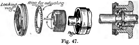
- Design "H" (Plate IV) carries both cones on a hard steel sleeve through which the spindle passes, as on the "Osmond," adjustment being by a movable cup turned with a peg spanner, the "disc adjustment." Two locking methods are described: the "Elswick" loose ring with peg and milled locking ring (Fig. 47), and the slit hub end clamped by a buttress-threaded ring used on the "Osmond."
- Crank spindle bearings are nearly always outside-facing with cup adjustment. Design "G" (Plate I) locks the cup with a square-headed set-bolt closing a slit lug; Design "H" (Plate III) uses a shaped cotter-pin bearing on the cup thread. The bracket is made as wide as possible to reduce crank overhang, and the American device in Design "H" forges half the spindle onto each crank, the two halves wedging into a hard steel sleeve with right and left-hand threads.
- Pedal bearings are inward-facing, the cups formed in the ends of a sleeve over the spindle. Garratt compares the usual fixed cone at the crank end (Design "H") with Design "G"'s fixed cone outboard and loose cone doubling as a lock-nut, warns about hardening cracks at the thread root, and prefers a square-bar rubber pedal to rat-trap on grounds of comfort and shoe wear.
- Sperm oil in small quantities is the usual choice, black oil oozing out being a sign of a soft race. Garratt argues that at 240 revolutions a minute a hub is not a high-speed bearing and recommends heavy mineral cylinder oil injected with a small brass syringe, one machine so treated since August 1894 has never needed adjustment, which also excludes mud and water and gives "a ghost-like silence" in running.
- Covers spokes, rims and tyres. Opens with the abandonment of radial spokes screwed into the hub flange, which broke off leaving the threaded stub buried in the flange and transmitted drive by shearing and bending instead of direct pull.
- Traces the change from radial spokes screwed into the hub flange, with the drilling out of broken ends that this entailed, to tangent spoking in both wheels, noting that a pure running wheel would properly be radially spoked but that ease of attachment settled the matter.
- Fig. 48 shows why two opposed sets of tangent spokes are needed, one taking drive and the other braking or reaction, and how tightening one set against the other lets the whole wheel be brought up taut.
- The ideal is a pivot pin at right angles to the spoke through duplicated flanges (Fig. 49), approached in practice by the "New Rapid" arrangement (Fig. 50a). The usual plan bends the spoke end and heads it through the flange (Fig. 51); the "Elswick" flange carries a bulb round its edge (Fig. 52) to stop spokes bursting out.
- Brass or gun-metal nipples (Fig. 53), round through the rim and squared outside for the spanner notch, with a spherical head seating on a washer inside the rim. Spokes of 15 or 16 gauge are best butted, thinned in the middle rather than jumped up at the ends, and Garratt prefers inside and outside spokes kept independent and unwired to the usual wired-and-soldered crossing.
- Introduces the tyre as the thing that must be understood before rims can be discussed, and sets up the general problem of making a good pneumatic.
- Resistance comes from adhesion to the road, ploughing through inelastic material, and above all the work absorbed in compressing the tyre. Because air recovers almost perfectly while rubber recovers sluggishly, pneumatics are decisively better than solid or cushion tyres; a pneumatic also swallows small road irregularities and has abolished the broken spokes and loose nuts of the solid-tyre era.
- Compares the "Woods" rubber sleeve valve (Figs. 58, 59a), whose sleeve wastes a great deal of pumping effort and eventually perishes, the similar Ross-Courtney (Fig. 59b) with a separate flat seat and rubber washer, and Lucas' mechanical check valve (Fig. 60), which Garratt now uses exclusively and which lets an 8 in. pump inflate even tandem tyres. A footnote records that the 1900 Lucas valve will have a left-hand threaded plug.
- Side-slip on greasy roads is worsened by a tall rider, a high gear and a wide tread, and is best met by even pedalling rather than by tread patterns. Garratt finds a plain cover, or at most the concentric ridges of the "Palmer," "Clincher," "Scottish," "Fleuss" and "Trench," wears better and punctures less than any humped "decoration," whose hollows flip flints and pins into the casing and whose humps are torn off by brakes.
- Describes the Westwood section for wired tyres (Fig. 61), with its two shelves, central channel and tubular rolled edges, and the two-piece double hollow rim used with Bartlett-method tyres (Fig. 62). Holes must be drilled rather than punched; the flanged "Woollen Spoke Washer" (Fig. 63) supports the nipple head. Most Bartlett rims come from the Jointless Rim Co., spun from pressed steel pans (see Engineering, 20 September 1895); wooden rims persist with single tube tyres.
- Defines gear as the diameter of the equivalent direct-driven wheel, then defines force, work and power, Garratt's own climb of 199 feet in five minutes at 208 lbs. works out at about a quarter of a horse-power. He insists that crank length and gear height are questions of physiology, not mechanics, and dismisses "inventions" claiming to create energy.
- The rear sprocket screws on with a right-hand thread and is locked by a left-hand ring so back-pedalling cannot loosen it. For the front, Garratt prefers the Designs "G" and "H" method, a hollowed boss forged with the crank, the wheel screwed on and held by three set-screws, as used by Humber, over three forged arms bolted to the wheel (Fig. 64) or the sleeved boss through which the cotter-pin passes (Fig. 65), still used on the "Elswick."
- A crank is twisted at the pedal end and bent at the boss, so the section should be round outboard and deeper inboard. Garratt prefers a rectangular section throughout with well-rounded corners: it distributes material correctly, helps nickel plating to adhere, and a flat straight front makes a bent crank far easier to straighten by the roadside.
- Plain radial arms stamped in one piece with boss and rim suit ordinary roadster sprockets, but the very large fashionable wheels need more support or the rim runs untrue and the chain works badly. Garratt recommends the Fig. 64 scheme of three stout arms carrying an outer ring of many light ones, and dismisses the fanciful designs that "look like designs for church windows."
- The hardened block chain (Fig. 66), tempered steel blocks coupled by softer side plates on rivets, one inch pitch, is the simplest and one of the best. Uniform pitch is vital and demands perfect machinery; Perry's "Humber" chain (Fig. 67) bushes the rivet in pen steel with the split at the back, doing away with the shouldered rivets of the Hans Renold pattern. Fig. 68 explains the clearance that lets blocks drop straight onto the driving faces of the teeth.
- The twin roller chain (Fig. 70) is a block chain with a composite roller block, transferring sliding from the dirty tooth faces to the clean roller bore, worth having only when the chain runs exposed in dust or mud. The finer chain with evenly pitched rollers (Fig. 71) doubles the number of tooth spaces and spreads wear, though its narrower roller-to-tooth contact is a slight disadvantage.
- One rivet is replaced by a steel screw threaded through a side plate and secured by a very thin square lock-nut. Garratt insists on keeping the lock-nut, having found recessed-head screws without one apt to work loose and drop out while riding.
- To shorten, keep the end carrying the threaded side plate, file off a rivet head and drive it through with a punch, bending the side plates clear. Lengthening is harder: send it to the maker to be riveted properly, or fit an extension with a coupling screw, an ordinary repairer will almost certainly leave a link out of pitch and spoil the whole chain.
- A slack chain may come off or catch the pedal end of the crank, wrecking the machine; a tight one causes friction, a cracking noise and a wheel that stops abruptly instead of oscillating. Garratt concludes it is far better a trifle slack than a trifle tight, and that a gear-case removes the danger entirely.
- Oil should be brushed into each joint and the surplus wiped off, or powdered graphite brushed in with two polishing brushes, dirtier work, but dust does not stick to graphite as it does to oil. Exposed chains must be thoroughly cleaned periodically however unpleasant the job.
- Garratt regards the well-fitted metal "Carter" gear-case, those on the "Elswick" being the finest, as second only to the pneumatic tyre among cycling improvements. He substitutes cylinder oil for the makers' ordinary lubricating oil so the machine can be laid on its side or turned upside down, warms the case with a spirit lamp to settle the dirt, and flushes with paraffin; two of his machines have run since 1895–96 with virtually no chain adjustment.
- Fig. 72 shows the fixed case, soldered to the frame and the most dust-proof, but awkward to repair if bent in a collision. Fig. 73 shows the detachable pattern, split horizontally and held by a fin clamped to the frame engaging grooves in both halves, fixed by two screws, easy to take apart, fiddly to reassemble.
- Slides on both sides of the case rear allow for chain adjustment but are apt to catch in spoke ends. Garratt puts his on the inside (Fig. 74) in fairly stout metal, free horizontally but captive vertically, so the hub itself guides and moves them automatically when the chain is adjusted, and reports no chatter against the hub.
- Celluloid, leather and combination cases are cheap and better than nothing, especially on a lady's machine or a mixed tandem, but are untidy, must be dismantled for cleaning and are never as dust-proof as a properly fitted metal case. Garratt warns that a gear-case should be treated like a dress-coat and always made to order for the machine.
- Gear is found by dividing the number of teeth on the crank sprocket by the number on the back hub and multiplying by the wheel diameter: nine and twenty-seven teeth on a 28 in. wheel give 84 in., ten and twenty-nine give 81.2 in.
- At a given speed the pull on the chain is proportional to the diameter of the back chain-wheel and is entirely independent of the gear height or the crank length. (The scan lacks printed pages 167–176, which carried the chainless, bevel, Acatene and epicyclic two-speed gears; the text resumes on page 177 with variable gears.)
- The closing chapter on the fittings a rider actually handles, handle-bars, brakes, saddles, foot-rests and free pedals, splash-guards, luggage carriers, spanners, cyclometers, bells and lamps.
- The upright tube is shaped and lapped round the horizontal bar and brazed (Fig. 80), which Garratt considers entirely satisfactory; brazing the bar into a lug in front of the post is "unmechanical" and done only for fashion. The "Elswick" uses a bored and machined T-shaped stamping with an externally graduated post, first-rate but extravagant.
- Contrasts the upright position (Fig. 81), in which Garratt says Nature intended a man to ride and from which the greatest benefit is derived, with the racing crouch (Fig. 82) adopted only to cut wind resistance, a psychological question usually answered by the expression on the rider's face.
- Indiarubber wears best and cements on easily but goes sticky in hot weather; felt is much used and probably most suitable; cork is pleasant to hold but wears badly and does not adhere well to the bar.
- Answers the riders who go brakeless on grounds of weight, arguing that a man with a brake descends faster and arrives refreshed while the brakeless rider is having "a hot and even anxious time of it" a quarter of a mile behind, the brake is a means of obtaining speed downhill, not of losing it.
- Divides brakes into tyre, rim and drum classes. Indiarubber is the best rubbing material for tyre brakes, its high coefficient of friction needing only light pressure; Hall's brake (Fig. 83) carries each block on a spindle like a pedal bar so the blocks can be turned over when worn.
- Front-wheel tyre brakes are worked by a plunger tube from a handle-bar lever; Garratt recommends hinging the block on an arm from a lug behind the crown as in Design "G" and putting the spring on the handle-bar (Fig. 84), where it cannot clog with dirt. Rear tyre brakes need rods and bell-cranks that rattle, and the pneumatic brakes used to avoid them are too slow and weak for an emergency stop.
- Blocks of fibre, leather or rubber are pressed against the inside faces of the steel rim. The outstanding example is E. M. Bowden's back-wheel brake (Fig. 85), whose flexible cord is a stranded tension wire inside a closely wound wire helix, the blocks carried on a horseshoe against the seat stays and pulled either by a twisting handle with internal cord or by a grip lever. Garratt notes it solved the problem of braking the rear wheel of a tandem, but cautions against very thin Bartlett-pattern rims.
- A drum on the driving hub encircled by a leather-lined steel band, familiar from winches, cranes, motor cars and traction engines. The small movement of a grip lever forces high leverage and low clearance, so the band rubs; only a five or six inch drum works really well, and running the leather dry or resined makes the brake squeak and fade as it warms. Garratt suggests Bowden's device (Fig. 86) as the answer to the transmission problem.
- Covers the seat pillar, horizontal tube and clip, Garratt preferring Brooks' older under-frame and clip (Fig. 87) as a firmer attachment than the newer independent pattern. He defends sprung saddles such as the Brooks' B90 against the springless frames commonly seen, illustrates spring arrangements for men (Fig. 88) and either sex (Fig. 89), and discusses saddle shape, the depression along the ridge, and pressure on the perineum.
- Fork-clamped foot-rests (Fig. 90) should have a single outside bolt and no inside projections, and Garratt describes coasting six miles across northern moors in eighteen to twenty minutes. On free pedals he shows Morrow's Patent Clutch (Fig. 91), a roller ratchet on inclined tooth backs, and the Wilkinson Sword Co.'s back-pedalling rim brake (Fig. 92) worked through a second silent ratchet on the crank spindle, judging free wheels of most value to ladies.
- Pressed sheet steel with beaded edges is the most permanent material, all fittings riveted and brazed since rivets alone work loose. The front guard is best hinged to an eye behind the crown through a brazed double eye (Fig. 93), with hard steel wire stays carrying screwed-on washers (Figs. 94, 95a, 95b) under the hub nuts; where that is impossible, as on the “Elswick” and “Osmond,” the stays go to the seat stays (Fig. 96) or to sprung pegs (Fig. 97).
- Reviews the four places luggage can go, in front of the head, on the handle-bar, in the frame, and behind the saddle, condemning the buckles and "rattle-traps" of trade-made bags. Turner's "Bi-Carrier" (Fig. 98b) is a strong detachable frame behind the saddle; Garratt himself uses a 16 in. by 8 in. wicker basket made by Mr. R. G. Moon of 12 Lower Park Row, Bristol in a waterproof canvas case (Fig. 99) strapped on with Lucas's "King's Own" handle-bar clips, and lists its 5 lb. 12 oz. touring contents.
- Every machine should leave the works with spanners that fit every nut and reach every bearing, a test few machines pass. Adjustable spanners are condemned as slovenly and destructive of nut corners; Fig. 100 shows a complete set for a machine built of B.S.A. fittings, the two spanners as supplied plus a home-made spring-steel screw-driver shouldered for pedal pins, the whole lot weighing only a few ounces.
- Explains the "Veeder" pattern in detail: a 2 in. cylinder on the front spindle, a five-armed star wheel driven by a spoke peg, and five figure rings read through a glass. Using the epicyclic train of Figs. 101–104, rings of twenty-three, twenty, nineteen and twenty-two teeth, he calculates that the wheel turns 728.33 times per "cyclometer mile" against 720.28 actual, the difference roughly offsetting tyre compression.
- A small nickel map-measuring wheel, like a watch on a chain, giving inches and feet on two hands and accurate enough on Bartholomew's reduced Ordnance maps. Garratt calls his cyclometer a toy but his rotameter almost a necessity, and notes they cost 4s. 6d. in nickel or 7s. 6d. in silver from any mathematical instrument dealer.
- Good-toned bells are now cheap and easy to pick out, but the choice between colza oil, paraffin, candle and acetylene lamps defeats him, all are a nuisance, and design and workmanship of body and back springs matter more than output. Since most lamps merely dazzle the rider and light a bright patch just in front, he concludes candles are the cleanest and most convenient way of simply showing the machine's approach.
Images in this book 106 pictures from 223 pages
Illustrations 12
 (opens in a new tab)
 Fig. 47. 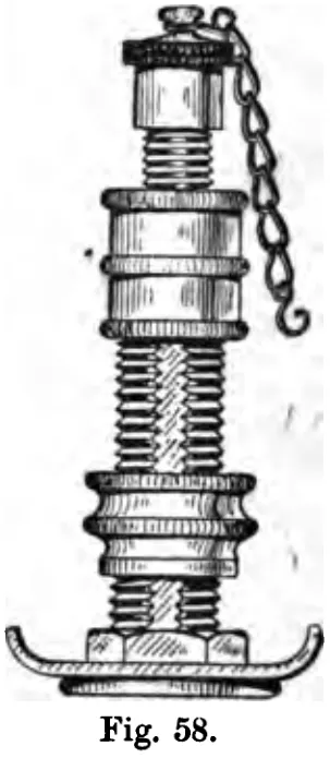 (opens in a new tab)
 Fig. 58. 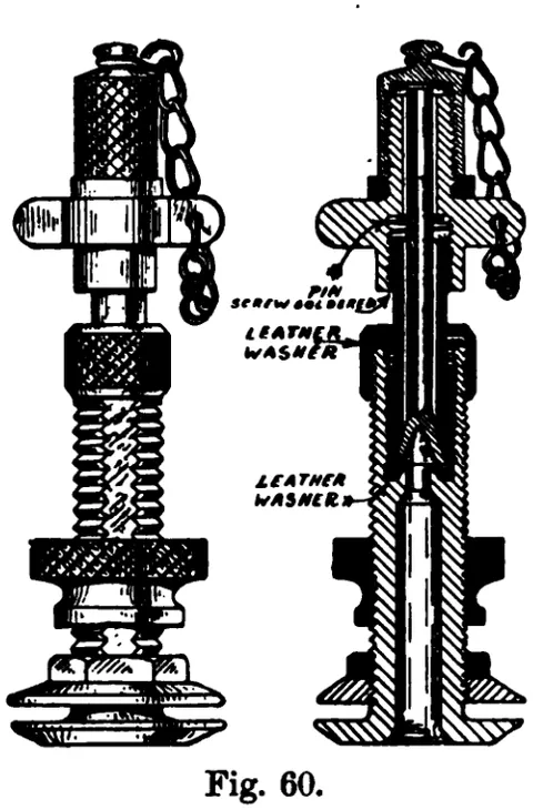 (opens in a new tab)
 Fig. 60. 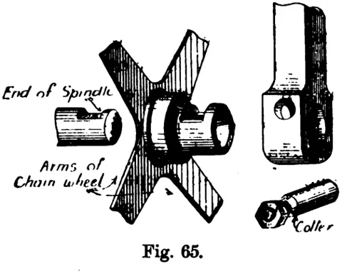 (opens in a new tab)
 Fig. 65. 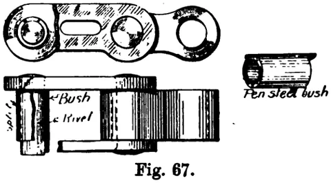 (opens in a new tab)
 Fig. 67. 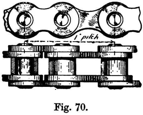 (opens in a new tab)
 Fig. 70. 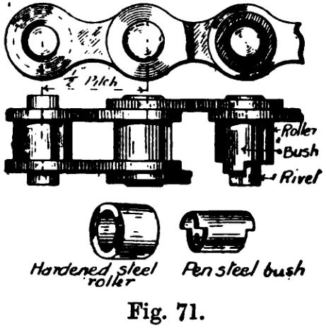 (opens in a new tab)
 Fig. 71. 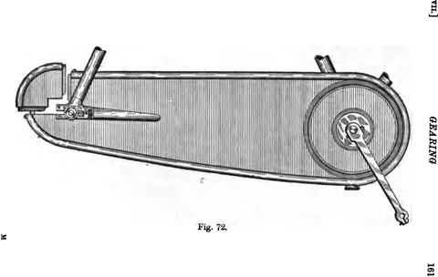 (opens in a new tab)
 Fig. 72. 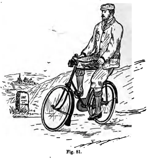 (opens in a new tab)
 Fig. 81 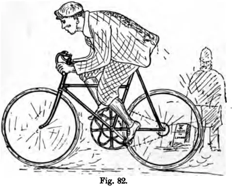 (opens in a new tab)
 Fig. 82 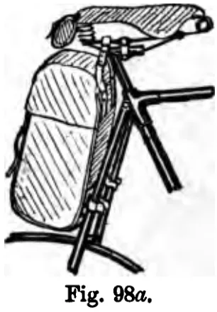 (opens in a new tab)
 Fig. 98a 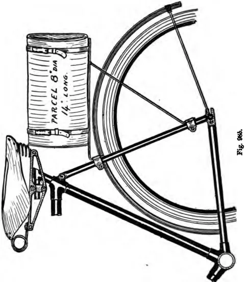 (opens in a new tab)
 Fig. 98b
Photographs 1
 (opens in a new tab)
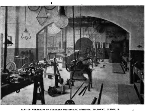
 Part of Workshops of Northern Polytechnic Institute, Holloway, London, N.
Diagrams 93
 (opens in a new tab)
 Fig. 1 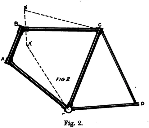 (opens in a new tab)
 Fig. 2 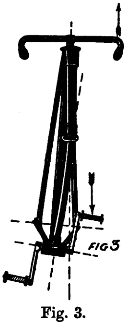 (opens in a new tab)
 Fig. 3 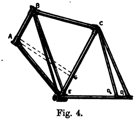 (opens in a new tab)
 Fig. 4 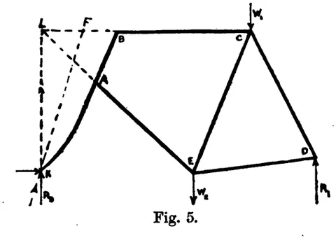 (opens in a new tab)
 Fig. 5 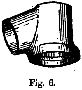 (opens in a new tab)
 Fig. 6 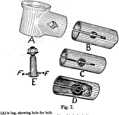 (opens in a new tab)
 Fig. 7 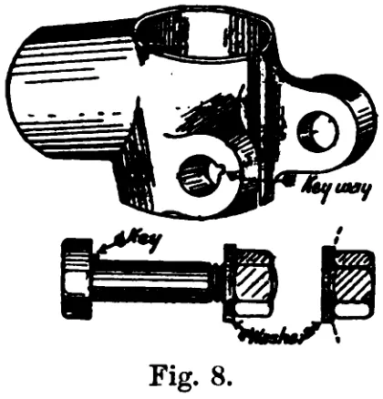 (opens in a new tab)
 Fig. 8 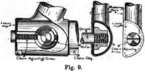 (opens in a new tab)
 Fig. 9 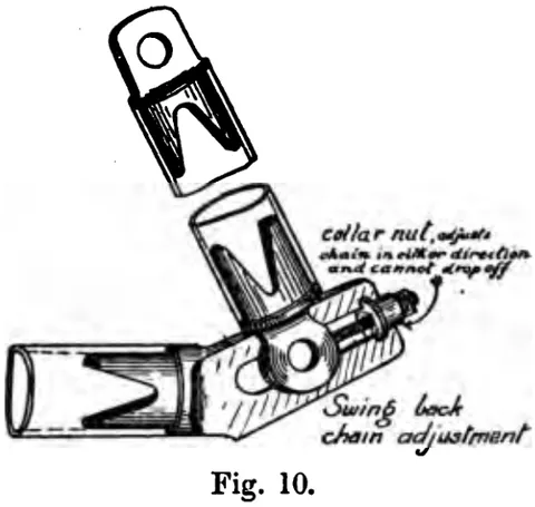 (opens in a new tab)
 Fig. 10 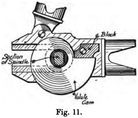 (opens in a new tab)
 Fig. 11 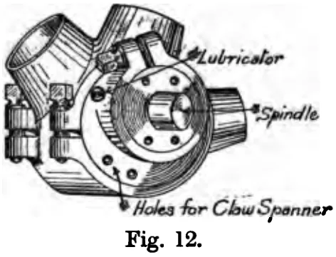 (opens in a new tab)
 Fig. 12 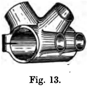 (opens in a new tab)
 Fig. 13 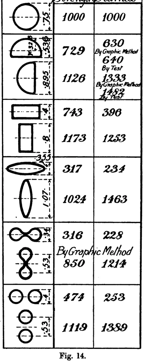 (opens in a new tab)
 Fig. 14 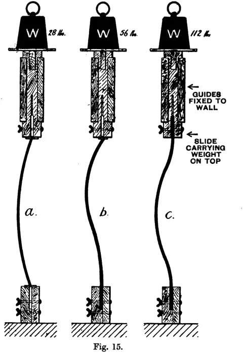 (opens in a new tab)
 Fig. 15 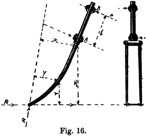 (opens in a new tab)
 Fig. 16 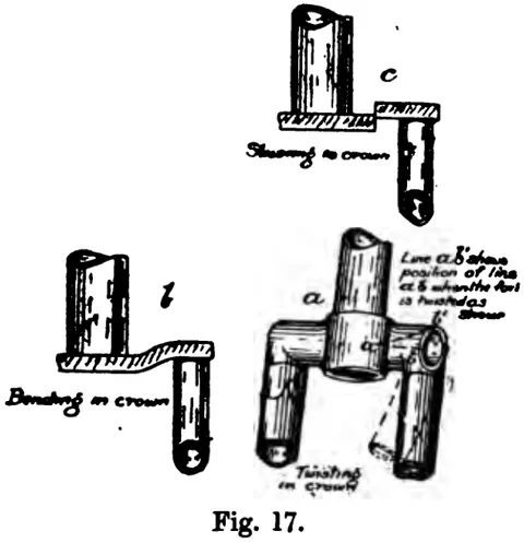 (opens in a new tab)
 Fig. 17 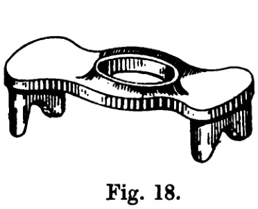 (opens in a new tab)
 Fig. 18 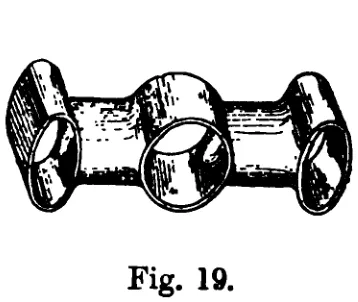 (opens in a new tab)
 Fig. 19 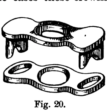 (opens in a new tab)
 Fig. 20 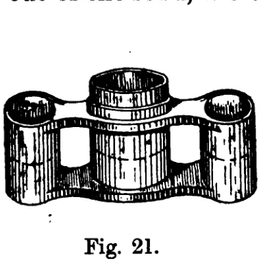 (opens in a new tab)
 Fig. 21 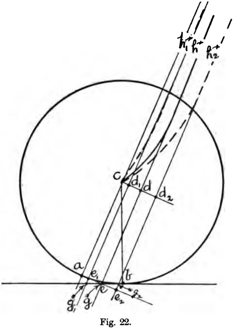 (opens in a new tab)
 Fig. 22 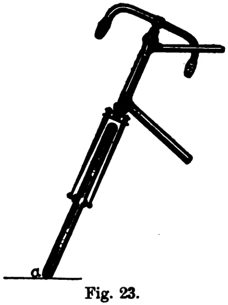 (opens in a new tab)
 Fig. 23 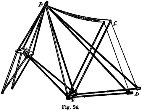 (opens in a new tab)
 Fig. 24 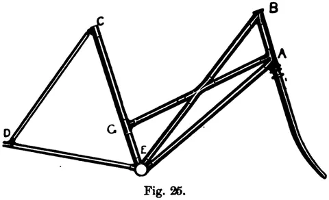 (opens in a new tab)
 Fig. 25 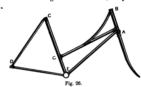 (opens in a new tab)
 Fig. 26 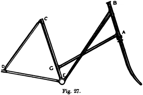 (opens in a new tab)
 Fig. 27 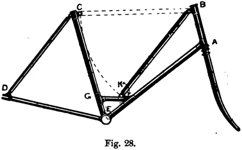 (opens in a new tab)
 Fig. 28 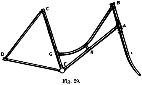 (opens in a new tab)
 Fig. 29 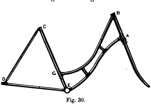 (opens in a new tab)
 Fig. 30 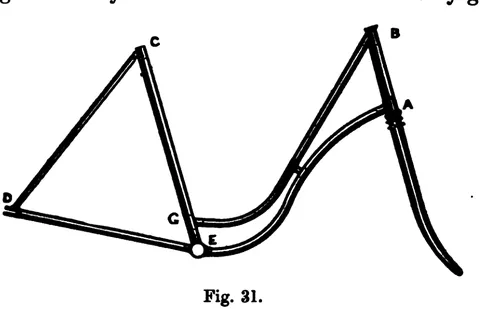 (opens in a new tab)
 Fig. 31 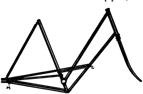 (opens in a new tab)
 Fig. 32 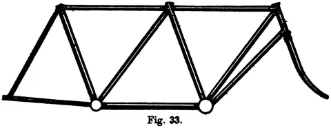 (opens in a new tab)
 Fig. 33 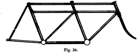 (opens in a new tab)
 Fig. 34 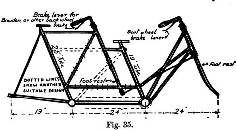 (opens in a new tab)
 Fig. 35 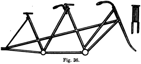 (opens in a new tab)
 Fig. 36 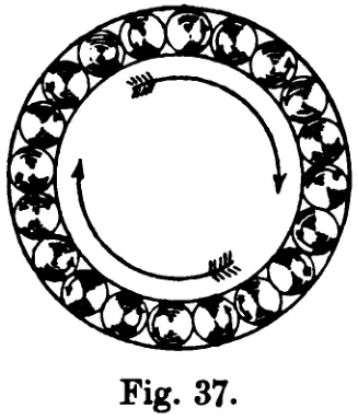 (opens in a new tab)
 Fig. 37. 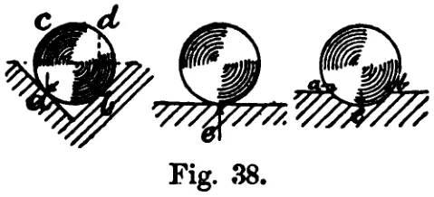 (opens in a new tab)
 Fig. 38. 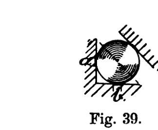 (opens in a new tab)
 Fig. 39. 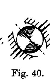 (opens in a new tab)
 Fig. 40. 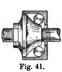 (opens in a new tab)
 Fig. 41. 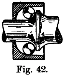 (opens in a new tab)
 Fig. 42. 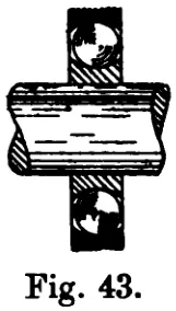 (opens in a new tab)
 Fig. 43. 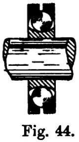 (opens in a new tab)
 Fig. 44. 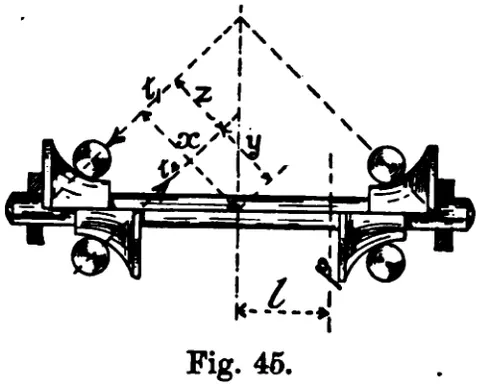 (opens in a new tab)
 Fig. 45. 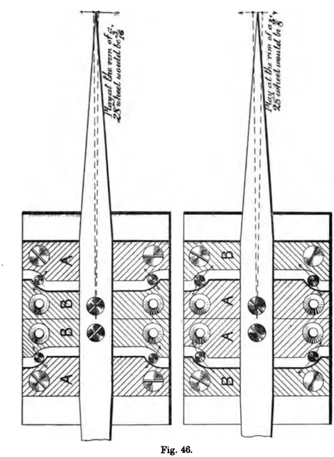 (opens in a new tab)
 Fig. 46. 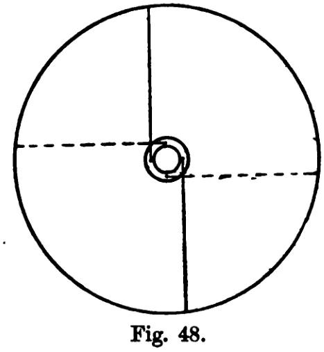 (opens in a new tab)
 Fig. 48. 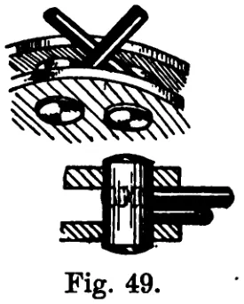 (opens in a new tab)
 Fig. 49. 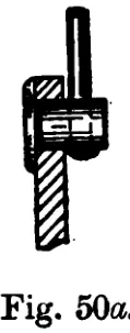 (opens in a new tab)
 Fig. 50a. 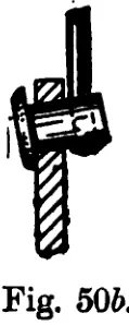 (opens in a new tab)
 Fig. 50b. 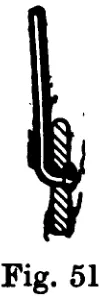 (opens in a new tab)
 Fig. 51. 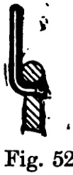 (opens in a new tab)
 Fig. 52. 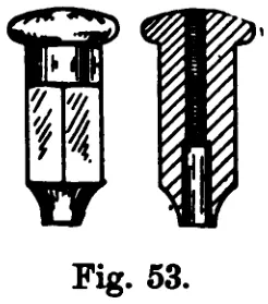 (opens in a new tab)
 Fig. 53. 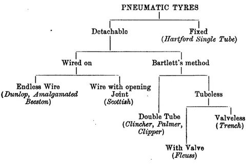 (opens in a new tab)
 Classification of Pneumatic Tyres 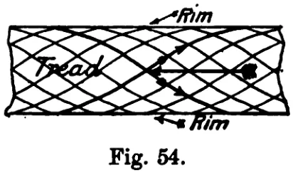 (opens in a new tab)
 Fig. 54. 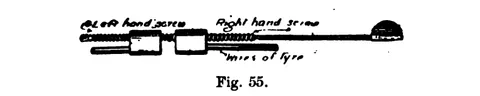 (opens in a new tab)
 Fig. 55. 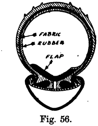 (opens in a new tab)
 Fig. 56. 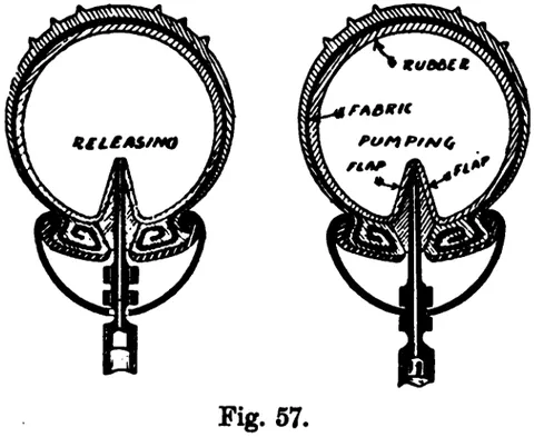 (opens in a new tab)
 Fig. 57. 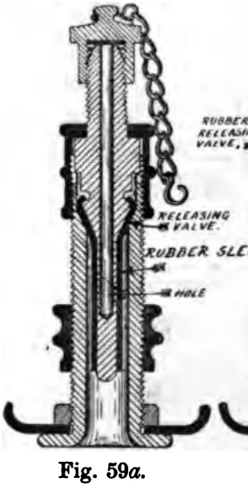 (opens in a new tab)
 Fig. 59a. 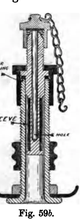 (opens in a new tab)
 Fig. 59b. 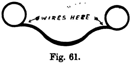 (opens in a new tab)
 Fig. 61. 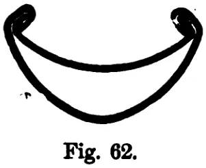 (opens in a new tab)
 Fig. 62. 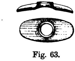 (opens in a new tab)
 Fig. 63. 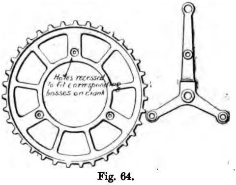 (opens in a new tab)
 Fig. 64. 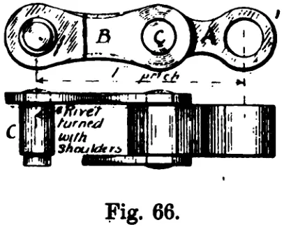 (opens in a new tab)
 Fig. 66. 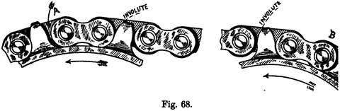 (opens in a new tab)
 Fig. 68. 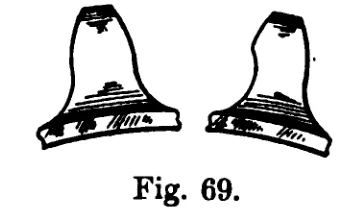 (opens in a new tab)
 Fig. 69. 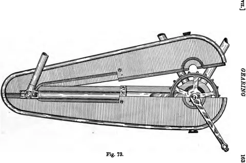 (opens in a new tab)
 Fig. 73 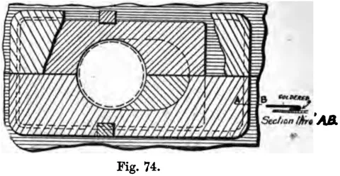 (opens in a new tab)
 Fig. 74 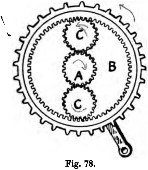 (opens in a new tab)
 Fig. 78 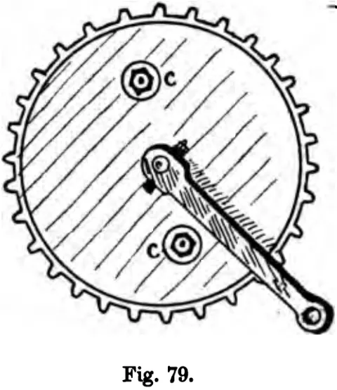 (opens in a new tab)
 Fig. 79 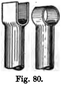 (opens in a new tab)
 Fig. 80 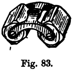 (opens in a new tab)
 Fig. 83 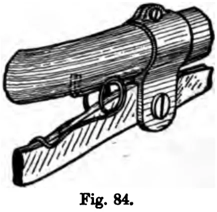 (opens in a new tab)
 Fig. 84 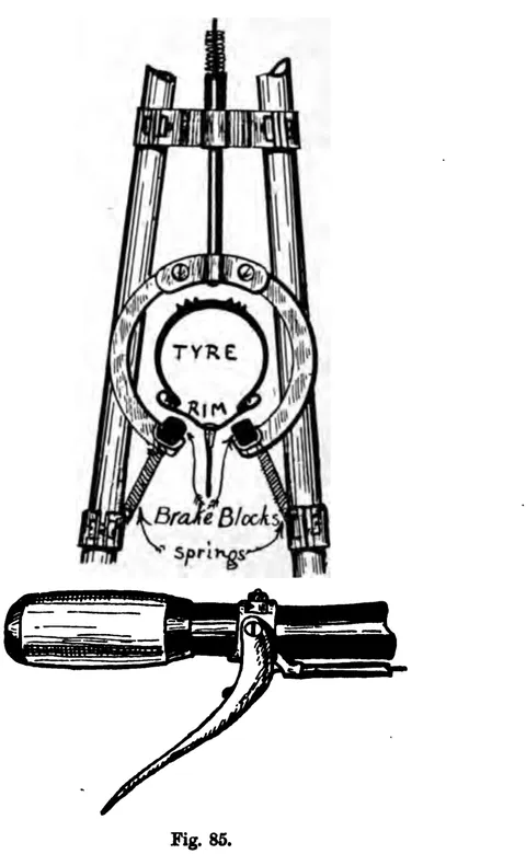 (opens in a new tab)
 Fig. 85 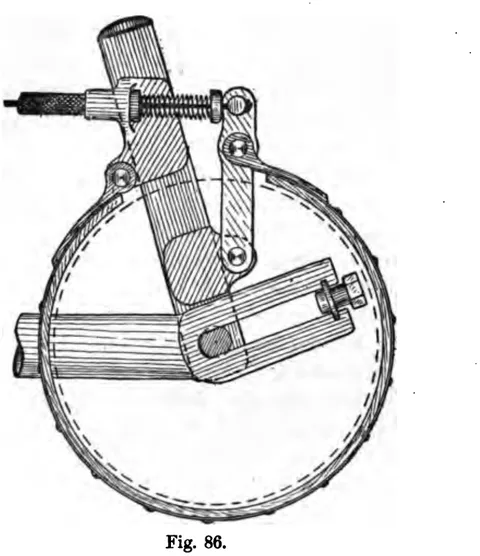 (opens in a new tab)
 Fig. 86 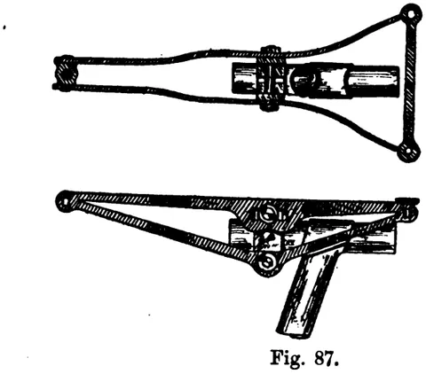 (opens in a new tab)
 Fig. 87 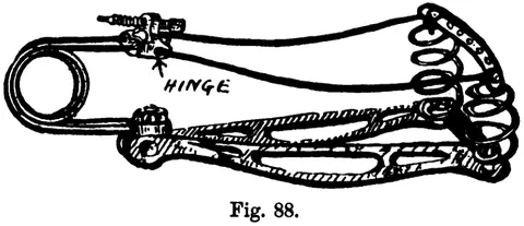 (opens in a new tab)
 Fig. 88 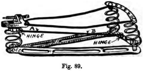 (opens in a new tab)
 Fig. 89  (opens in a new tab)
 Fig. 90 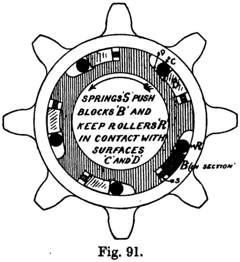 (opens in a new tab)
 Fig. 91 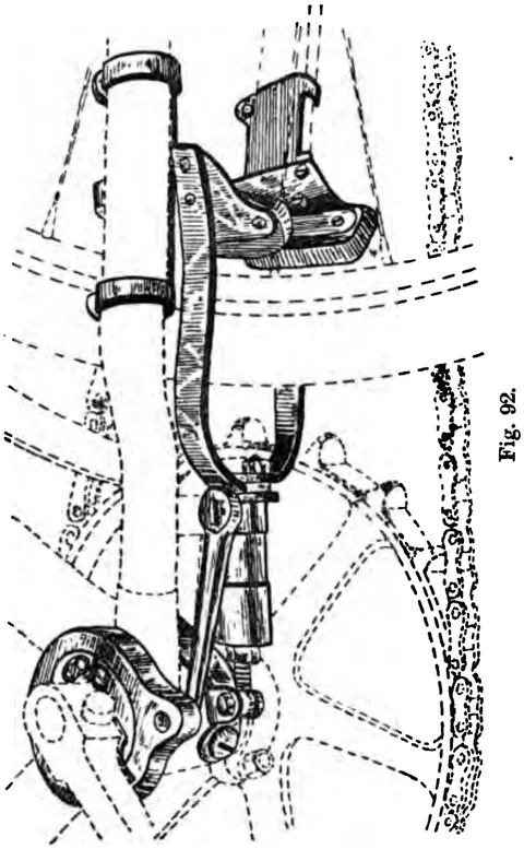 (opens in a new tab)
 Fig. 92 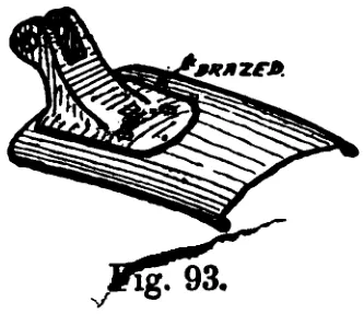 (opens in a new tab)
 Fig. 93 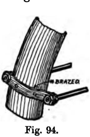 (opens in a new tab)
 Fig. 94 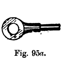 (opens in a new tab)
 Fig. 95a 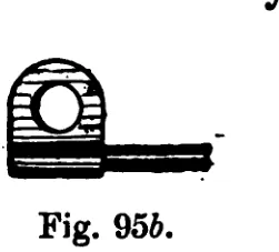 (opens in a new tab)
 Fig. 95b 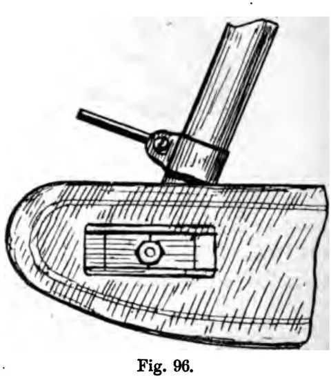 (opens in a new tab)
 Fig. 96 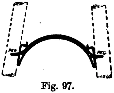 (opens in a new tab)
 Fig. 97 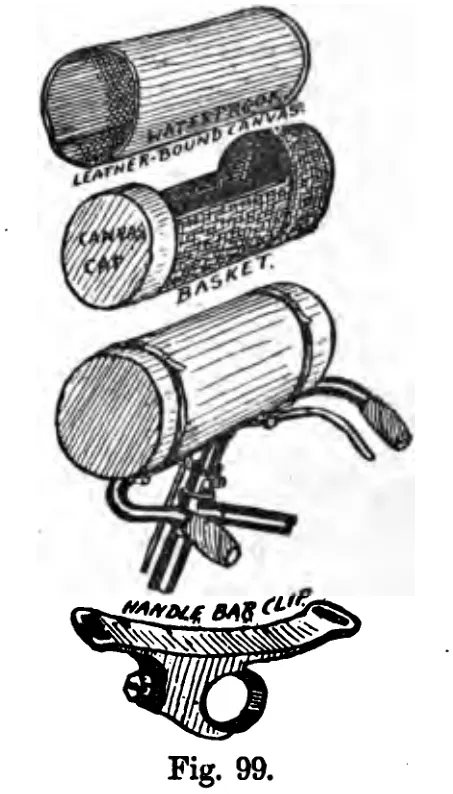 (opens in a new tab)
 Fig. 99 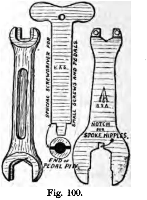 (opens in a new tab)
 Fig. 100 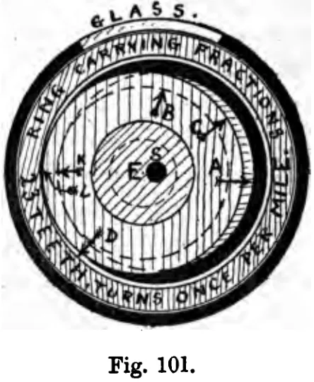 (opens in a new tab)
 Fig. 101 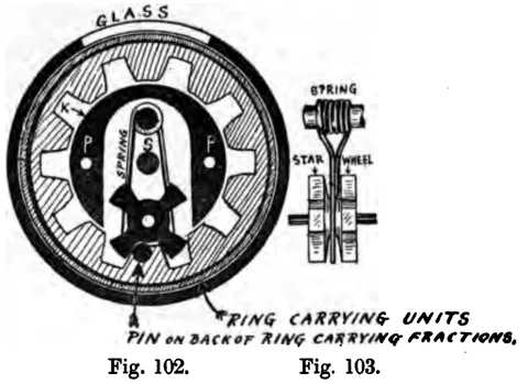 (opens in a new tab)
 Fig. 102. Fig. 103. 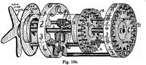 (opens in a new tab)
 Fig. 104